Breezaire Fan RPX900D User Manual
Browse online or download User Manual for Unknown Breezaire Fan RPX900D. Breezaire Fan RPX900D User's Manual
- Page / 54
- Table of contents
- BOOKMARKS
- Assembly 1
- Instructions 1
- IMPORTANT NOTICE 3
- Tools Required cont 4
- RPX ASSEMBLY INSTRUCTIONS 10
- Illustrated 11
- SPIRE NUT - P/No FAS 115 13
- BOLT NUT WASHER 14
- M6x20 M6 6x14mm 14
- M8x30 M8 8x19mm 15
- Motor Pulley Attachment 17
- GRUB SCREW 18
- 5/16 BSW 19 mm Long 18
- P/No SCR433 18
- SCREW - Phlp 20
- P/No 9610013 20
- RIVET 5X12 mm P/No FAS 032 21
- RIVET 3.2X8 mm P/No FAS 300 28
- Clean and Test Cooler 41
- Completed RPX 900D 41
- Washers part numbers 42
- Bolts and nuts part numbers 43
- Panels part numbers 45
- Panels part numbers, cont 46
- Misc. part numbers 47
- Misc. part numbers, cont 48
- RPX 900 'D' KIT 50
- PADS ASSEMBLY 51
- HARDWARE KIT 9655147 51
- RPX PALLET SPECIFICATIONS 52
- RPX 900D EXPLODED VIEW 53
- WIRING DIAGRAM 54
Summary of Contents
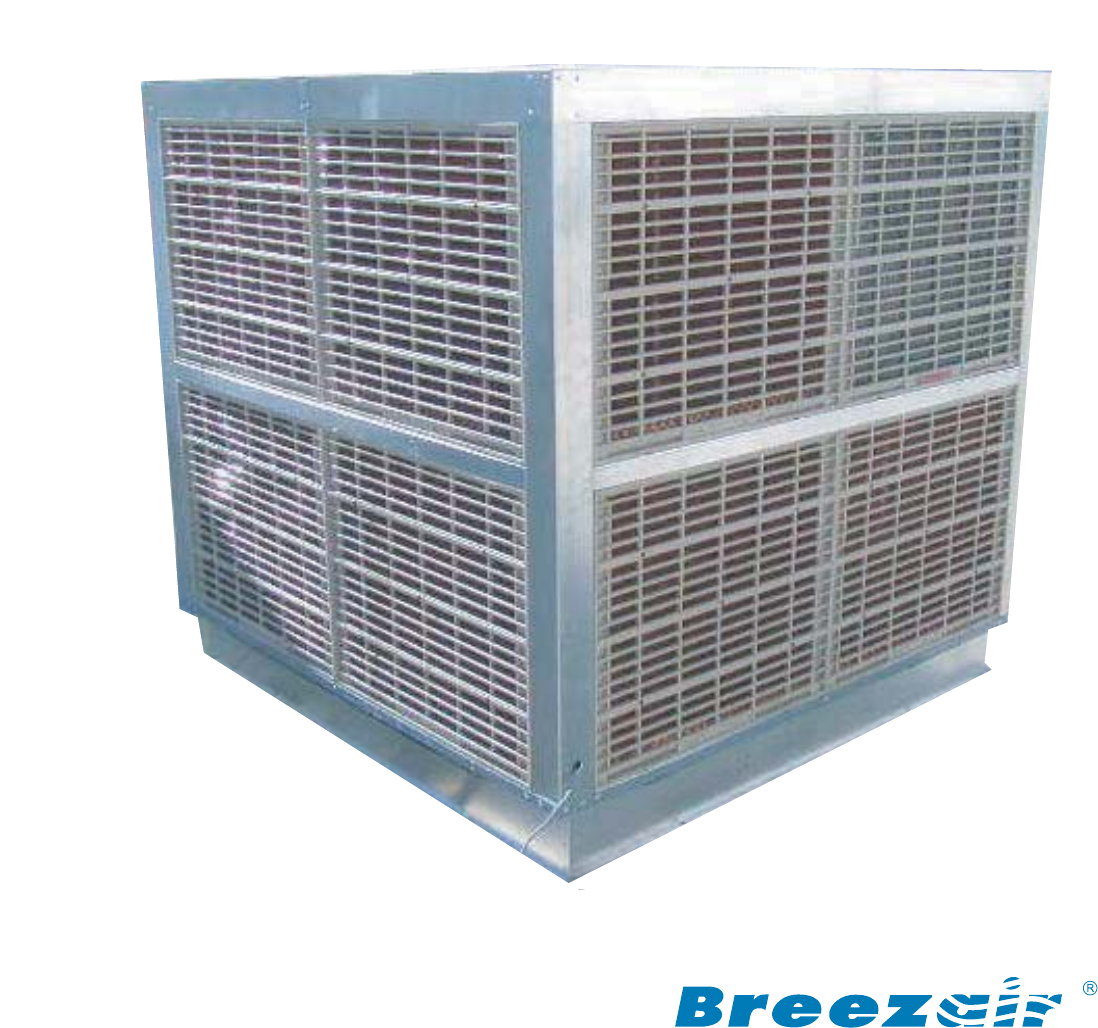
INDUSTRIALEVAPORATIVEAIR COOLERSRPX900DAdvanced natural coolingAssemblyInstructions
RPX ASSEMBLY INSTRUCTIONS10Installing Top Channel.Install Top/BearingChannel to VerticalChannels.Part N/o 623139Secure Channels.Tighten all bolts.Repe
RPX ASSEMBLY INSTRUCTIONS11Apply a generous bead ofsilicone sealant alongFan Housing and Tank.Fan HousingTankPlace Flashing Angleto Fan Housing and Ta
RPX ASSEMBLY INSTRUCTIONS12Secure FlashingAngle to Fan Housingand Tank, with suppliedscrews: Total 10 places.Note: If end of fan housingbows inwards a
RPX ASSEMBLY INSTRUCTIONS13Use crane to tilt cooler.Silicone sealantbetween Fan Housingand Tank,apply thick bead toall four sides.Fit spire nut to end
RPX ASSEMBLY INSTRUCTIONS14Prepare Motor and Controls. Step 1 of 4.Securing Control Boxpanel to Motor Platform.Place Control Box andwater pump assembl
RPX ASSEMBLY INSTRUCTIONS15Use crane and fit electricmotor to platform,align holes andsecure withsupplied fasteners.Secure Motor to Platform.Repeat fo
RPX ASSEMBLY INSTRUCTIONS16Feed seven wires from the electrcal control box wiringloom through the motor terminal cover opening.Attach all wires and se
RPX ASSEMBLY INSTRUCTIONS17The motor pulley attachesto the motor shaft via aTaper Lock Bush screwedto the Pulley.Do not fully tighten Bushlocking scre
RPX ASSEMBLY INSTRUCTIONS18Fit 460 mm AluminiumPulley to the fan shaft.Use suitable straightedge, align Fan Pulleyto Motor Pulley.Align Fan Pulley and
RPX ASSEMBLY INSTRUCTIONS19Use a suitablebelt tensionmeasuring tool,Set forrecommendedbelt tension.Deflec tion (cm) 1Force (Kg) 1.5/1.7Apply tension t
RPX ASSEMBLY INSTRUCTIONS2INDEXDescription PageIndex 2Important Notice/ Tools required 3Installing Fan Housing to Tank 1/5 5Installing Top Channel 10S
RPX ASSEMBLY INSTRUCTIONS20Use pump bracketsas templatedrill 4 mm holes.Position the two pumpsat the corner of the tank,nearest control box.Secure pum
RPX ASSEMBLY INSTRUCTIONS21Connecting the water system.Connecting the Water Inlet and FloatInstalling the Anti-Vortex panels.Connect waterhoses to pum
RPX ASSEMBLY INSTRUCTIONS22Remove plasticprotective film.Note: Hole locationon corner pillar.Repeat for all corners of Base Frame.Corner Pillar.Plasti
RPX ASSEMBLY INSTRUCTIONS23Align two tabs onCentre Rail to slotson Corner Pillar.One Rivet,for each end.Apply siliconeto folded tag.Corner Pillar.Cent
RPX ASSEMBLY INSTRUCTIONS24Top Rail Installation. Step 1 of 2.Note: Tab at eachend of rail.Remove protectiveplastic cover.Rivet UniversalBracket to To
RPX ASSEMBLY INSTRUCTIONS25Fit Top Rail toCorner Pillar.Repeat same for all Top Rails.Use suitable plierstwist Top Rail end tabinside Corner Pillar.Th
RPX ASSEMBLY INSTRUCTIONS26Base Frame.Bottom Rail.Place BottomRail to inside edgeof Base Frameand Rivet, to eightpoints.Completed AssemblyTop, Centre
RPX ASSEMBLY INSTRUCTIONS27Centre Pillar InstallationSelect Centre Pillar and slidethrough Centre Rail slot.Centre Rail.Centre Pillar.Bottom Rail.Slig
RPX ASSEMBLY INSTRUCTIONS28Align holes on WaterSpreader to Top Railand Rivet.Water Distributor Cap.Water Spreaders.Repeat same for other three sides.W
RPX ASSEMBLY INSTRUCTIONS29Fit Distribution Capto top of WaterSpreader.Note: Position ofDistribution Cap toWater Spreader.Repeat same for allWater Spr
RPX ASSEMBLY INSTRUCTIONS3IMPORTANT NOTICETools RequiredThe assembly of evaporative air conditioning units has the potential to create Occupational He
RPX ASSEMBLY INSTRUCTIONS30Cooler is fitted with two Water Pumps.R/H side Water Pumpsupply hose.Typical hose connectionto Water Spreders Inlet.8 place
RPX ASSEMBLY INSTRUCTIONS31Typical Hose Connection toWater Spreaders. D&T Models.Water Pump (2)Supply hose.Incorrect lengthWater supply hose.Hoses
RPX ASSEMBLY INSTRUCTIONS32Select T Model Cabinet Top,place to suitable work frame.Apply small bead of Siliconealong cut out inside line ofrivet holes
RPX ASSEMBLY INSTRUCTIONS33Note: Position ofCabinet Topjoined section.Place Cabinet Top onto Corner Pillars.Cabinet Top Installation. Step 1 of 2.
RPX ASSEMBLY INSTRUCTIONS34Repeat same for all corners.Remove plasticprotective cover,from corners ofCabinet Top.Cabinet Top.At this stage tworivets o
RPX ASSEMBLY INSTRUCTIONS35Use SuppliedBraces todiagonallysquare cooler.Fitall4BracesIf necessary drill 5 mm hole Distance between holecentres 1868mm.
RPX ASSEMBLY INSTRUCTIONS36Repeat same for other side.Drill two 12.5mm holesthrough Top Channeland Cab Top.Drill one 6mm holeto centre Top Channel.Not
RPX ASSEMBLY INSTRUCTIONS37Fit screw and washer,to centre hole of TopChannel, through toplastic washersand Top Channel.Use suitable pliers tohold Spir
RPX ASSEMBLY INSTRUCTIONS38When completed,remove allsquaring braces.Attach Lifting Eyenutto CoolerRepeat same forother three liftingEyenuts.Fit bolt a
RPX ASSEMBLY INSTRUCTIONS39Fasten thru CabinetTop Rail and Bracket.Repeat same forother three sides.Fit Nylon Washer betweenCab Top and UniversalBrack
RPX ASSEMBLY INSTRUCTIONS4Tools Required cont.Screwdriver No3. Spanners 10 and 13mmHex Key 4mm. Hex Key 5mm.Metal twist drill 5mm Metal twist drill 6.
RPX ASSEMBLY INSTRUCTIONSPlace Bleed Sticker onCorner Pillar over holePass bleed tap valvethrough hole openingand fit rubber Grommetover valve body.Ca
RPX ASSEMBLY INSTRUCTIONS41Clean and Test Cooler.Completed RPX 900DStep 1: Check that all fasteners are tightly secured,and all riveting is completed.
RPX ASSEMBLY INSTRUCTIONS42Washers part numbers.Washer 14x25x1.5mm. SSP/No 802138Washer13x44x2.5mm G/BondP/No 608372Nylon WasherP/No 629872Washer 9x25
RPX ASSEMBLY INSTRUCTIONS43Bolts and nuts part numbers.P/No SCR433P/No 628271 P/No 628288Grub screw 5/16 BSW 19mm long.Nut M6 Nyloc SS. Nut M8 Nyloc S
RPX ASSEMBLY INSTRUCTIONS44Screws and rivets part numbers.P/No FAS032Rivet 5x12mm Al.P/No FAS300Rivet 3.2x8mm Al.P/No FAS204Rivet 5x25mm Al.P/No 96100
RPX ASSEMBLY INSTRUCTIONS45Panels part numbers.Bottom RailP/No 626789Top RailP/No 626482Anti VortexP/No 627229Centre RailP/No 626772Corner PillarP/No
RPX ASSEMBLY INSTRUCTIONS46Panels part numbers, cont.Flashing Angle.P/No 100152Top/Bearing ChannelP/No 623139Base ChannelR/H P/No 623160L/H P/No 62716
RPX ASSEMBLY INSTRUCTIONS47P/No 822044.Bush Taper Lock..P/No 111500460mm Pulley.P/No 626987.125 x2A Mtr Pulley.P/No 025101Label Serial Number.P/No 111
RPX ASSEMBLY INSTRUCTIONS48Misc. part numbers, cont.P/No 609737.Overflow Assy.P/No 6266802 Speed switch Assy.P/No 200103Mounting block.P/No MIS508.Sil
RPX ASSEMBLY INSTRUCTIONS49Special jig to assist when securing Flashing Angleto Fan Housing.Place tool to centre of cooler, lever upwardsto push insid
RPX ASSEMBLY INSTRUCTIONS5Select Base Frame and Tank Assemblyfor Down discharge model.Place suppliedTemplate totop of Tank.Align holes withtemplate bo
50FAN HOUSING AND 'H' FRAME ASSEMBLY.RESERVOIR, BASE FRAME AND ACCESSORIES.RPX 900 'D' KIT.
51PADS ASSEMBLY.HARDWARE KIT 9655147.CABINET TOP 'D' ASSEMBLY.RPX 900 'D' KIT.
RPX PALLET SPECIFICATIONS52REV.DESCRIPTIONECN DATEDRN APPREVISIONSC3 Self drilling screws added to centre slats1046 24/03/2004RJK DPBRedrawn to curent
RPX 900D EXPLODED VIEW53625919201834285048424041175557 60 5626252327245253544431304735323361 2467298166311910151413124951 2038373661583916Pad -Small C
54WiFAN LOCLo/Hichange without notice. Please consult with your dealer to confirm the specifications of the model selected.Manufacturers and Designers
RPX ASSEMBLY INSTRUCTIONS6Installing Base Channels.Tank to accept squareend of Fan Housing.Installing Fan Housing to Tank. Step 2 of 5.Place Base Chan
RPX ASSEMBLY INSTRUCTIONS7Repeat process for other ends of Base Channels.At this stage do not fully tighten bolts.Refer to notes on Page 17.Installing
RPX ASSEMBLY INSTRUCTIONS8Installing Fan Housing to Tank. Step 4 of 5.Align and lowerbottom of fan housingto Tank cut out.Use lifting crane to raiseFa
RPX ASSEMBLY INSTRUCTIONS9Installing Fan Housing to Tank. Step 5 of 5.Secure Base Channelto Fan Housing.Fix two Screws betweenFan Housing and BaseChan
© 2020, manymanuals.com. All rights reserved. | 0.318 s |
 Manymanuals.com
 Manymanuals.de
 Manymanuals.fr
 Manymanuals.it
 Manymanuals.pl
 Manymanuals.cz
 Manymanuals.es
 Manymanuals-pt.com
Comments to this Manuals